Attack from Mars
Mini-Saucer LED KitTM
How to Install the AFM Mini-Saucer LED Kit
|
The AFM-LED kit was designed to be non-intrusive. You can install the kit in your Attack from Mars pinball machine without making any
permanent modifications to your game.
The AFM-LED printed circuit board will be mounted in the backbox, just like any other board. First, turn off your game and wait for 5-10 minutes for things to discharge. Next, unlock the backglass, then unplug and remove the backglass assembly, and place it somewhere safe. Inside the backbox you will see several circuit boards. In the upper-left corner of the backbox, you should see a bare area with four squares cut out of the metal backplane. 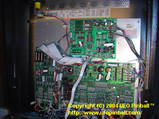
Attack from Mars backbox overview 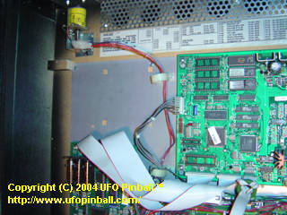
Close up of the AFM-LED installation area Install the four standoff clips included with the kit in the metal backplane. Pinch the ends together till the bottom of the clip fits inside the square, then release such that the "feet" of the clip slide behind the metal backplane. You may need to temporarily loosen the screws that mount the metal backplane to the wood of the backbox. Once the standoffs are installed, re-tighten the screws to the metal backplane. You may now install the board. 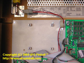
Upper-left backbox area with the four standoffs installed Using the screws and washers supplied, mount the board with the black interface plugs facing to the right. The board should be screwed in hand-tight, which will help the board make good electrical ground contact. As long as you are there, it might be worth hand-tightening the rest of the boards as well. 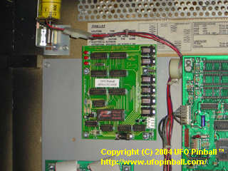
The AFM-LED board installed in the backbox Now, it is time to install the wiring harness. In order to do this, you will need to locate header J138, and driver transistor Q25, both on the Power Driver Board. 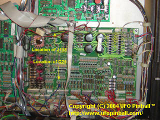
Locations of J138 and Q25 on the Power Driver Board First, take the wiring harness supplied and plug it in to the AFM-LED printed circuit board. The connector with three wires is the one that plugs into the AFM-LED board at header J7. Take the other connector (with only two wires) and route the wires down to the top of the Power Driver Board, and then to the right. Along the top of the Power Driver Board, locate connector J138. Plug the other connector in here. The board draws power here, directly from the Power Driver Board. 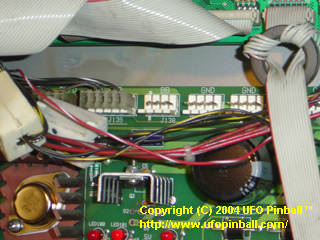
AFM Power Driver Board connector J138 (before) 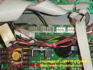
AFM Power Driver Board connector J138 (after) Once this is completed, you should only have a blue-purple wire left with a ring on the end. Take this wire and route it straight down, between the CPU and Power Driver Board. At the bottom of the Power Driver Board, begin pulling the wire to the right. About 1/3 of the way in, you should see banks of driver transistors ... the one you want is marked Q25. This connection is what links the AFM-LED board to the Mother Ship on the playfield. Specifically, it is linked to the tab of the driver transistor for the #906 flasher bulb under the green dome. If you are having trouble finding Q25, refer to the earlier guide. Insert the smaller screw provided, with the head of the screw facing the right, through the hole in the metal tab of Q25. The metal ring on the end of the blue/purple wire goes on next, followed by the nut that has the washer attached. Hand-tighten the nut, and make sure that no metal parts connected to Q25 touch any metal parts on any of the nearby driver transistors. 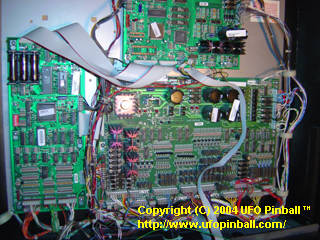
Overview of the Power Driver Board 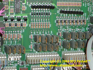
Close-up of driver transistor Q25 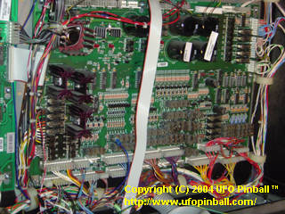
AFM-LED connector mounted to driver transistor Q25 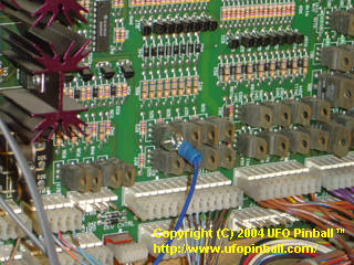
Close-up of Q25 connection 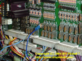
Close-up of Q25 connection (screw side) Now that the board is properly installed, our next step is to work on the saucers. Installation of the mini-saucer LED units needs to be done with the proper orientation, or the animated lights feature will not look right. The best way to do this would be to remove all six of your saucers. If you examine the holes on each saucer closely, you should notice that the mold was uneven, and some of the holes came out smaller than the others. The one that is the smallest is will be used as the #1 LED position. 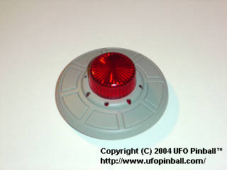
Close up of the holes on the saucers plastics Once you have located your #1 LED position. Take a mini-saucer LED unit, and flip it so that the LEDs face away from you. Please note that two of the solder tabs will be colored. Between these two colored tabs is LED #1. Gently mount the LEDs into the saucer plastic such that LED #1 fits into the hole previously selected. Using a small jewelers flat-head screwdriver, insert each LED into the corresponding hole, and push until they are firmly seated. 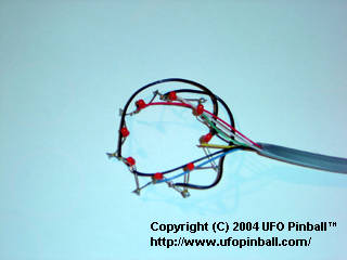
Mini-saucer LED unit 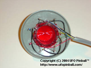
Installing the mini-saucer LED units 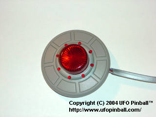
Mini-saucer with the LED unit properly installed Once you have completed all six saucers, you are ready for installation. At this point, however, it is probably worth testing the saucers to ensure that nothing was broken during installation. You can power-up the game and plug each saucer into the board, one at a time, to test that all the lights are functioning. When you are finished testing your saucers, you should power down and prepare to install them. The following instructions will show you how to mount the saucers, and what to do with the wires. This is just mounting the saucers themselves, we'll route the wires under the playfield when we are done. Please note that Saucer #6 has a longer cable than the rest of the saucers. Be sure to mount this one properly, or you will have trouble when you try to pull out and/or raise the playfield to work on your game!!! Saucer #1 is located to the left of the entrance of the Lobster ramp. Install it so that the wire for the LEDs is located towards the playfield ... somewhere between the 6 and 7 o'clock position. 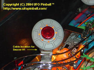
Location of cable for Saucer #1 Saucer #2 is located in the far back left corner of the playfield. Install it so that the wire for the LEDs is located towards the left wall of the game ... at approximately the 9 or 10 o'clock position. 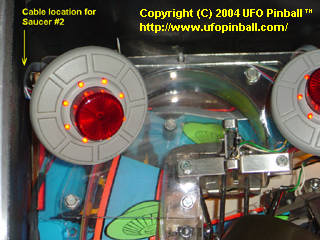
Location of cable for Saucer #2 Saucer #3 is located to the right of Saucer #2, near the Mother Ship. Install it so that the wire for the LEDs is located towards the back wall of the game ... at approximately the 11 or 12 o'clock position. 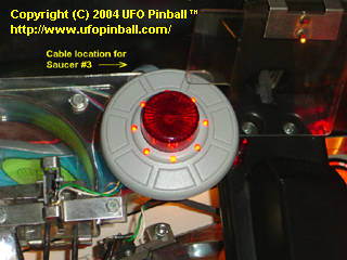
Location of cable for Saucer #3 Saucer #4 is located to the left of the Cow ramp, near the Mother Ship. Install it so that the wire for the LEDs is oriented along the wall of the ramp (towards the left) ... at approximately the 10 or 11 o'clock position. 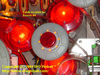
Location of cable for Saucer #4 Saucer #5 is located towards the back right corner of the playfield. Install it so that the wire for the LEDs is oriented along the wall of the ramp (towards the left) ... at approximately the 10 o'clock position. You should feed the wire behind the pole just to the left. 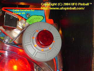
Location of cable for Saucer #5 Saucer #6 is located along the right wall of the game, about midway up the playfield. Install it so that the wire for the LEDs is located towards the playfield ... at approximately the 7 o'clock position. 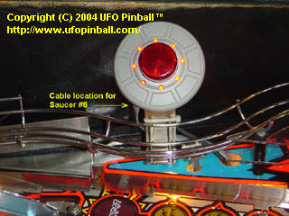
Location of cable for Saucer #6 Now that you have all six saucers mounted, you can feed the wires under the playfield. This may require removal of the Lobster ramp, as the wires for Saucer #1 feed through a hole directly below this ramp. The wires for Saucers #2 and #3 feed through a hole located at the far back of the playfield, which is also easier to access once you have moved the Lobster ramp aside. 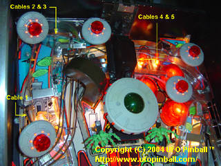
Location of cables for Saucers 1-5 The wires for Saucers #4 and #5 feed through a hole located below below the arm that's holding the Mother Ship, just underneath the "Lock" ramp entrance. If your ramp is nice and clean, you should be able to see the hole that you are after, and can feed these wires through without having to remove anything on the game. 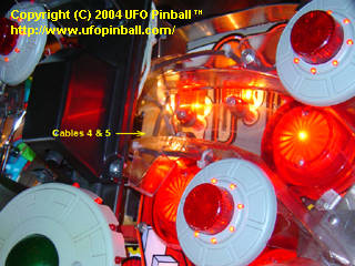
Location of cables for Saucers 4 & 5 The wires for Saucer #6 feed through an easily accessible hole, located just to the right of the saucer. 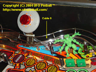
Location of cable for Saucer 6 Now that you have completed feeding the wires under the playfield, pull the playfield out and gather the wires together. Run the wires towards the back of the game, and up through the hole leading to the backbox. Run the wires themselves between the CPU board and the Power Driver Board ... go under the ribbon cables. Plug each saucer wire into the corresponding plug. The plugs are numbered 1-6 with plug #1 closer to the bottom of the board, and plug #6 at the top of the board. Once you have connected all the saucers, turn on the power and enjoy your new Attack from Mars Mini-Saucer LED Kit!! 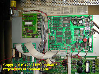
AFM-LED Kit installed in the backbox 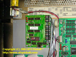
Close-up of the AFM-LED Kit installed in the backbox 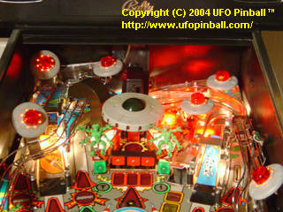
Playfield view of the AFM-LED Kit, fully installed You will probably want to double-check the orientation of your saucers, and adjust them if they appear off. The opening chase sequence should be largely synchronous between the six saucers. |

This page is under construction
Back to the Main Page
Copyright © 2004 UFO PinballTM
www.ufopinball.com