Williams / Data East
Display Saver KitTM

Installing the Display Saver Kit
| WARNING: The Display Saver board controls high voltage for the displays. These voltages are around +100 and -100 volts and is very dangerous. Take care with the Display Saver board as you would with any other board in the backbox, and do not touch the board while the game is on. |
|
The display saver board should be installed between your main power board, and your display
board(s). The display saver kit includes an extension connector to properly insert the board
in-line with your display power connector.
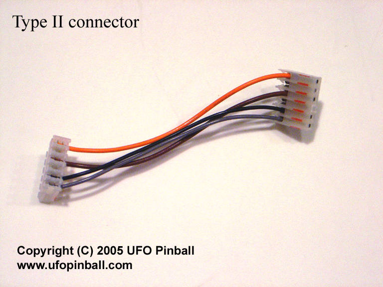
From the beginning of the solid-state era through mid-Sys11B, Williams used what we will call the "Type I" connector. When the power supply board was redesigned (starting with Taxi), Williams changed the pinouts to the 6-pin display power connector to what we will call the "Type II" connector. Before you begin, you will need to know if your game uses the original (Type I) style connector, or the newer (Type II) style connector. 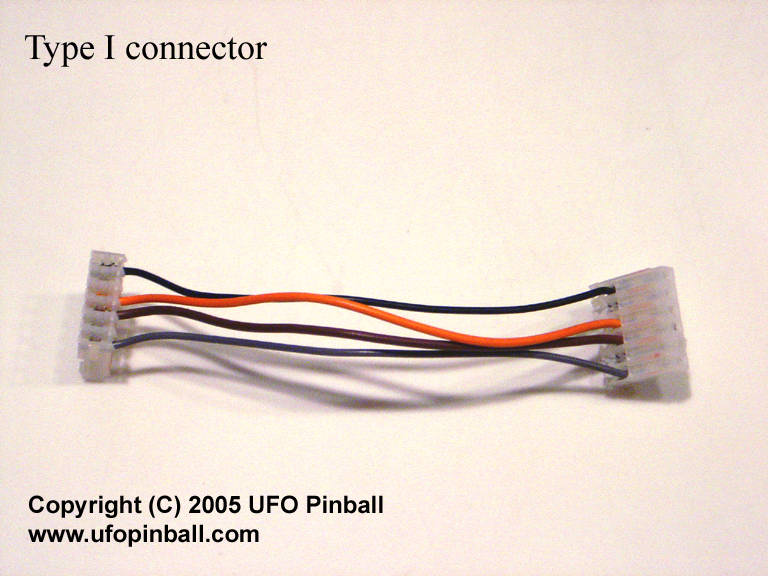
Type I connector (games):
Type II connector (games):
Unfortunately, I am not very familiar with Data East hardware. Please double check your connectors against the Type I and Type II pinouts (above), and E-Mail me if you are unsure. Data East games:
If your game uses Type I connectors, you will be using headers J1 (power side) and J2 (display side). If your game uses Type II connectors, you will be using the J4 (power side) and J3 (display side) headers. The two types of connectors are keyed differently, and they are not interchangable. Turn your game off and open the backbox. Inspect the power board and locate the 6-pin power connector. These wires should lead to the main display controller board, where a similar 6-pin connector delivers power to the displays. You may install the Display Saver board into the chain on either on the power board end, or the display controller end. Power Board Installation: To install the kit on the Power Board end, you will need to locate a proper mounting location in the backbox. On some games, you can screw it into the roof or wall of the game. On some older games, there is more shielding. You may need to skip to the Display Controller Installation section. Mount the board firmly before you proceed. Next, unplug the 6-pin power connector from the main power board. Plug this connector into the appropriate plug (J2/J3) along the long end of the Display Saver board. Take the extension cable that came with the kit and connect it to the appropriate plug (J1/J4) along the short end of the Display Saver board. Connect the other end to the main power board, where you removed the original power cable. Skip down to "Configuring the Display Saver Board". Display Controller Installation: To install the kit on the Display Controller end, you will need to locate a proper mounting location behind the GI panel. Mount the board firmly before you proceed. Be certain that the board will not touch anything when you close the GI panel. Next, unplug the 6-pin power connector from the Display Controller board. Plug this connector into the appropriate plug (J1/J4) along the short end of the Display Saver board. Take the extension cable that came with the kit and connect it to the appropriate plug (J2/J3) along the long end of the Display Saver board. Connect the other end to the Display Controller board, where you removed the original power cable. Configuring the Display Saver Board: Initially you will want to set both the +100v and -100v jumpers to "Step 0". This is a pass-through configuration, where your voltages are unaltered. Power up the game and verify that your displays are running properly. The power board can take a few minutes to warm up to full power. You may wish to leave the game on for a few minutes before you begin. Next you should power down, move the jumpers down a notch, then power up again. Each step reduces either the +100v or -100v line by approximately 1 volt. Keep doing this until you reach a point where the display voltage is too low to run properly. Move the jumpers up a notch or two until they reach a level where the displays are solid. The jumpers can and should be configured independently. The configuration of the jumpers is entirely up to you, and will be unique for each game. There is no pre-defined or default setting. Even when you find the optimum setting for your current set of displays, you may wish to push the voltage down even further to see what the displays will handle. If most of your displays are good, but one of the displays not doing as well as the rest, then you may wish to swap that one out and run the entire system at a lower voltage level. Maybe you can group all of the displays that require more power into one game and run just that machine at a higher display voltage. This technique will work better on older games (High Speed / Pin*Bot or earlier) than on some of the newer games (F-14 Tomcat and later), since Williams started putting all the displays on one large board in the later years. Some of the games produced just after the Williams/Bally merger (ie: Elvira and the Party Monsters) use independent displays, and would be a good candidate though. |
||||||||||||||||||||||||||||||||||||||||||||||||||||||||
Back to the Main Page
Copyright © 2005 UFO PinballTM
www.ufopinball.com