The Simpsons Pinball Party
Mini-Saucer LED KitTM
(Click to enlarge)
How to Install the Simpsons Pinball Party Mini-Saucer LED Kit
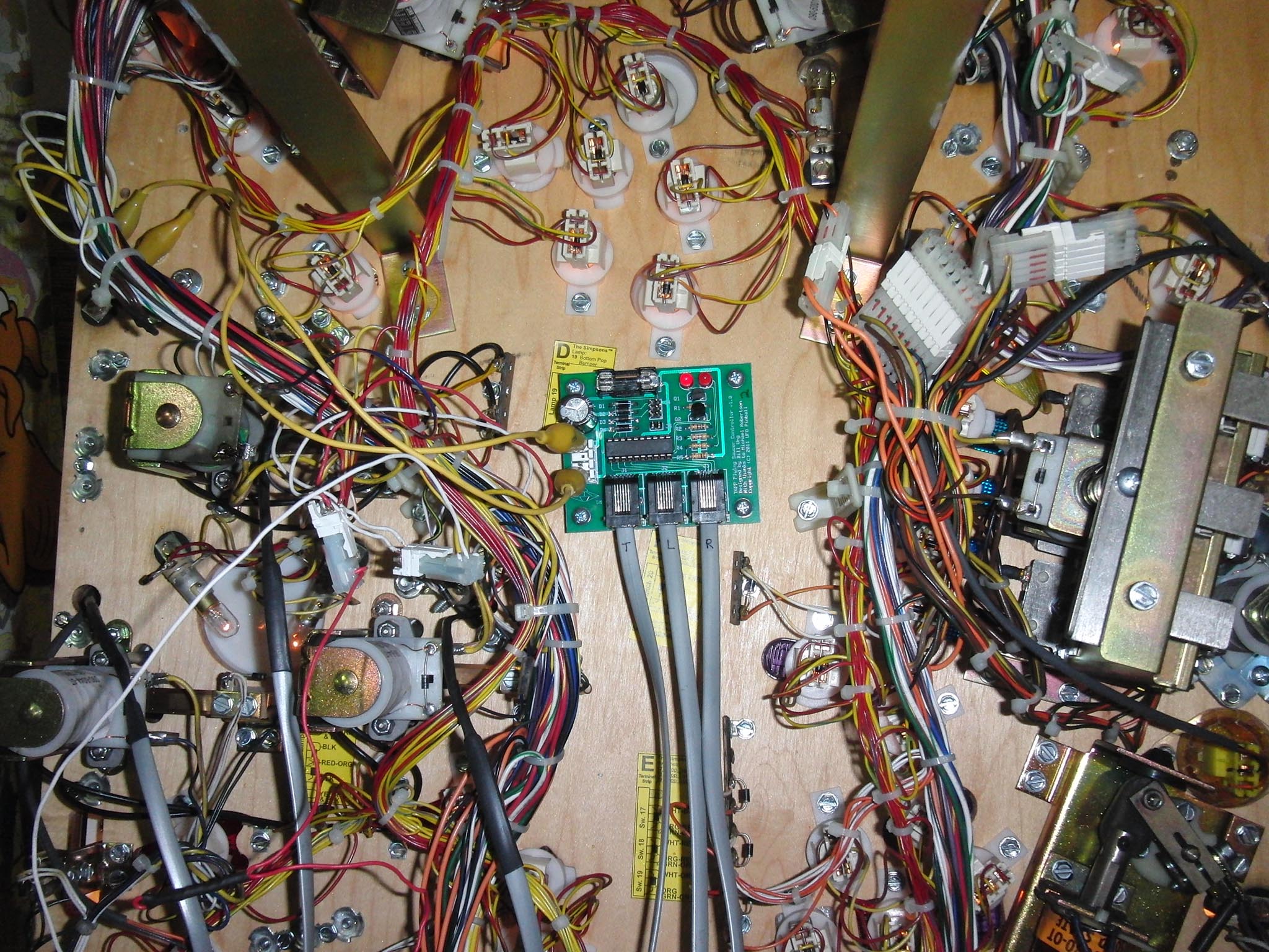
The TSPP-Saucer printed circuit board will be mounted under the playfield and is powered by the General Illumination circuit.
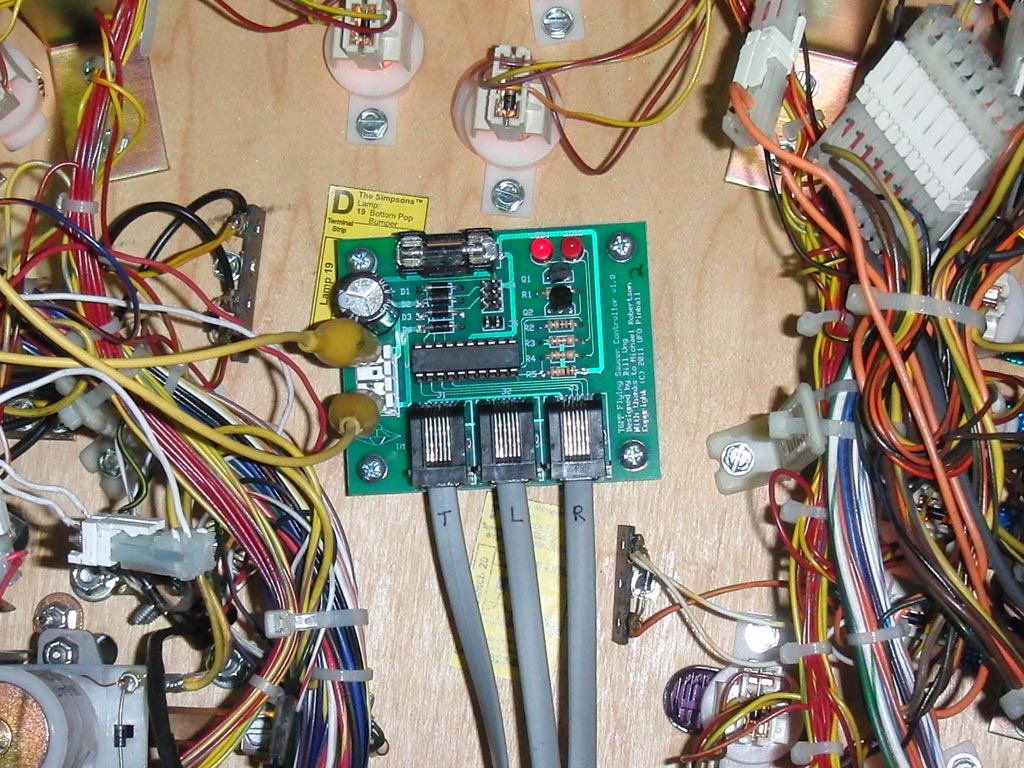
Mounting hardware is included with the board, you will be making four screw holes into the wood in the middle area where there is a lot of room.
The above picture is from TJ Beyer's game at the Pin-a-Go-Go in 2011 and does not include a proper power wiring harness. The finished product will include a wiring harness and bare wire connections on the end. The alligator clips were for testing purposes, you will need to actually solder the wires to ensure stability in a high vibration machine. You may solder the wires to any GI lamp, click on the picture above to see where we connected ours.
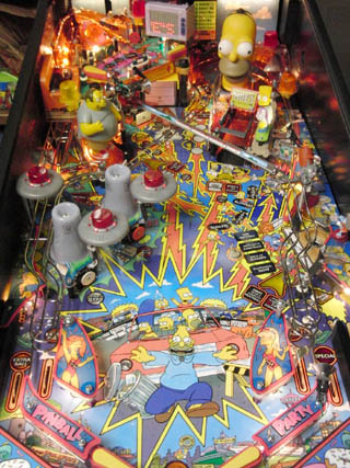
After installing the board, it's time to add the saucer mounts. The first saucer mount "Top" is already included with the game, and is located to the left of the cooling towers.
The other two saucer mounts will be added using the hex extenders. For each cooling tower, there is a standup target in front of it. Above the standup is a small plastic. Remove the nut on the right side of the plastic and install the hex extender. Place the clear plastic saucer mount on top of the hex extender, and secure it using a #6 washer and #6-32 3/8" screw.
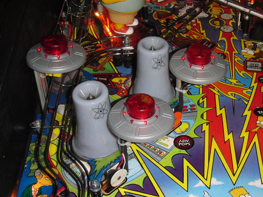
Carefully mount a grey plastic saucer to space the clear plastic saucer mount, this helps ensure that the grey plastic saucer won't rub up against the cooling tower plastic. Tighten the screws once you are happy with the spacing.
Install the leds in the grey plastic saucers as labelled on the cords. "T" is Top and goes on the upper saucer. "L" is Left for the left Cooling Tower and "R" is Right for the right Cooling Tower. See the AFM installation section for additional details. Once the LEDs are installed, mount the grey saucers to the clear plastic saucer mounts.
Feed the cables through the playfield, behind the nearby standup targets. You may need to remove the targets, feed the cables through, and then re-mount the targets.
Connect the saucer LED cords to the board from left-to-right, T-L-R.
Locate the "Pops Flasher" connector, this feeds to the "Top" saucer mount. The wire colors are Orange, and Violet-Green. There should be a Z-connector that you can pull apart. Once you have separated the Z-connection, the side nearest the flasher should have a female plug, and the side that goes back to the boards should have the male plug. Connect the Flashlamp Power Extender's female plug to the male plug that goes back to the backbox. Then, connect each of the three saucer mounts (female plugs) to one of the three male pins on the Flashlamp Power Extender.
Note: I don't actually own a Simpsons Pinball Party, so I am still working on gathering proper pictures to help illustrate these web pages.

Note: This page is still under construction
[
About/Features
|
Purchase
|
Install
|
F.A.Q.
|
Feedback
]
Back to the Main Page
Copyright © 2011-2024 UFO PinballTM
www.ufopinball.com