Attack from Mars
Mini-Saucer Expansion KitTM
How to Install the AFM Mini-Saucer Expansion Kit
Chapter 1: Preparing your game
(Click on pictures to enlarge)
|
The Attack from Mars Mini-Saucer Expansion kit is a fairly complicated install process. There are a lot of parts in the box, but don't be deterred. 
When it comes down to it, mostly it's going to be a matter of installing the wires properly. Most of them only fit one way, and all of them have properly color coded wires. After installing the board, there are only three keyed connections that go to the Power Driver Board and don't require any soldering or cutting of wires. Underneath the playfield, there are only four wires that will need to be desoldered and then reconnected to interface with my board. You should have wire stripping tools and a soldering iron available. Everything else is just running the cables, and of course installing the Attack Hallway LEDs ... which is mainly a mechcanical job. You'll need screwdrivers and nut drivers for this portion. The following instructions are meant to be fairly detailed, but if you have any questions, feel free to contact me. Preparing your game: Attack from Mars was an early WPC-95 game. To work properly with the AFM-Expansion board, the following items should be looked at first: 1) It is recommended diodes on the Power Driver Board (D25-D32) should be removed and replaced with jumper wires. The traces behind the diodes should be checked for burn marks, and additional jumper wires added as necessary. This was covered in a service bulletin from Williams/Bally: SB94. For the purposes of my kit, this change is recommended, but not required. If your Power Driver Board is in good shape, and intended only for home use, you can skip this item for now. Note: Work on the WPC-95 GI Diode section is covered on this website: click here. 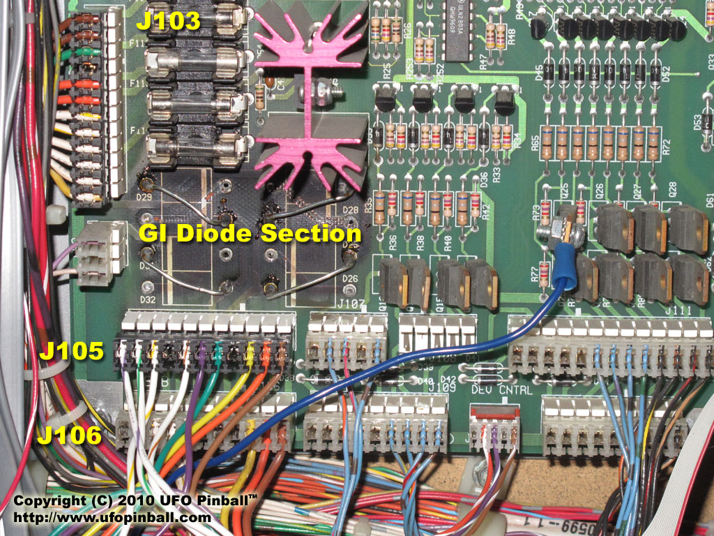 2) J103 (GI Input from Transformer), J105 (Playfield GI) and J106 (Backbox GI) should be checked for cracked/broken connections, and/or burned pins and connectors. All faulty connections should be addressed. 3) Verify that the all five GI strings (Brown, Orange, Yellow, Green and Violet) are in good working order. Note: Repair of the GI section is covered on Clay's website: click here. 4) Inspect the Jet Bumper lamps, verify proper wiring under the playfield for the lamps in the Jet Bumper body. The left and right jet bumpers should be on the Yellow GI circuit, and the bottom jet bumper should be on the Orange GI circuit. 5) Inspect the Jet Bumper mechanics and ensure all three jet bumpers are in good working order. Also verify that the switches are properly gapped and play with good action. If you cannot reach Super Jets, you will miss out on some of the features of this kit. Chapter 1: Preparing your game Chapter 2: Installing the board and connecting the cables Chapter 3: Wiring up the Super Jets and Attack Hallway LEDs Chapter 4: Installation testing and jumper settings Chapter 5: Troubleshooting |
Back to the Main Page
Copyright © 2010 UFO PinballTM
www.ufopinball.com