Attack from Mars
Mini-Saucer Expansion KitTM
How to Install the AFM Mini-Saucer Expansion Kit
Chapter 2: Installing the board and connecting the cables
(Click on pictures to enlarge)
|
1) Install the AFM-Expansion board by removing the two left-hand screws on the AFM-LED board, and fitting the AFM-Expansion board behind it, then replacing the screws. The boards will share these two screw holes. 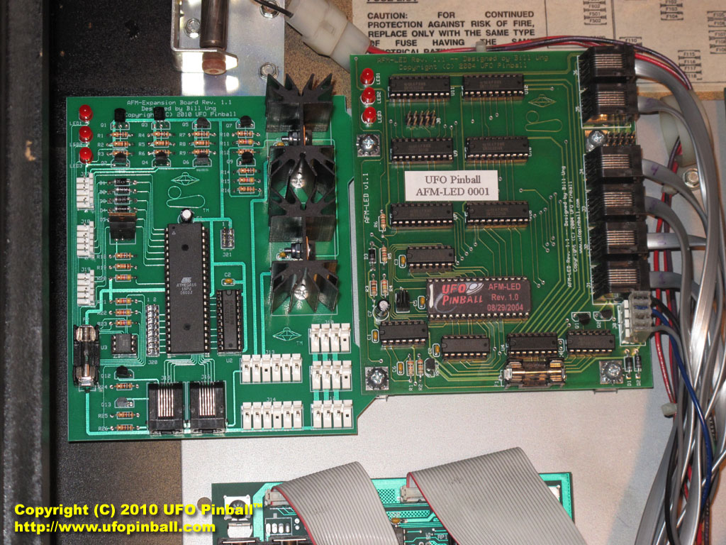 2) The Power Wiring Harness is about 1 foot long, with Grey (+5v), Black (GND) and Yellow (+12v) wires: 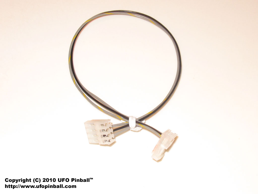 Install the Power Wiring Harness by connecting it to any one of the 4-pin power connectors (lower right corner, they are all the same), and plug the other end into J138 on the Power Driver Board. Move the existing AFM-LED power connector from J138 and plug it into an open 4-pin power connection on the AFM-Expansion board. This leaves one additional 4-pin power connector for future expansion. 3) The GI Wiring Harness is the one with Green and Purple wires, and the heavy-duty black IDC connectors: 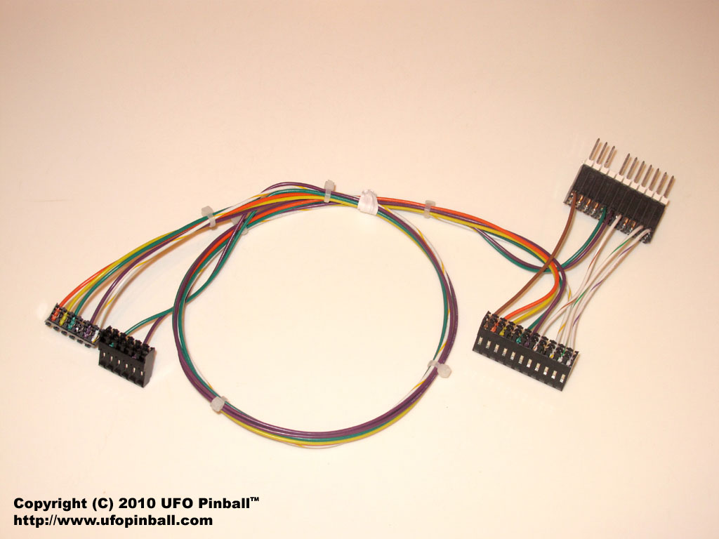 Starting with the end with the two six-pin connections, plug the header with only two wires into the bottom 6-pin connector (J14) on the AFM-Expansion board. The other one with five wires goes to the upper 6-pin connector (J13). The other end is a little more complicated. On the Power Driver Board, unplug the backbox GI connector from J105/J106 and plug it into the Z-connector of the GI Wiring Harness (the male connector). Plug the remaining end of the GI-Wiring Harness into J105/J106. 4) The "J110" Wiring Harness is about three feet long with a 16-pin black socket attached: 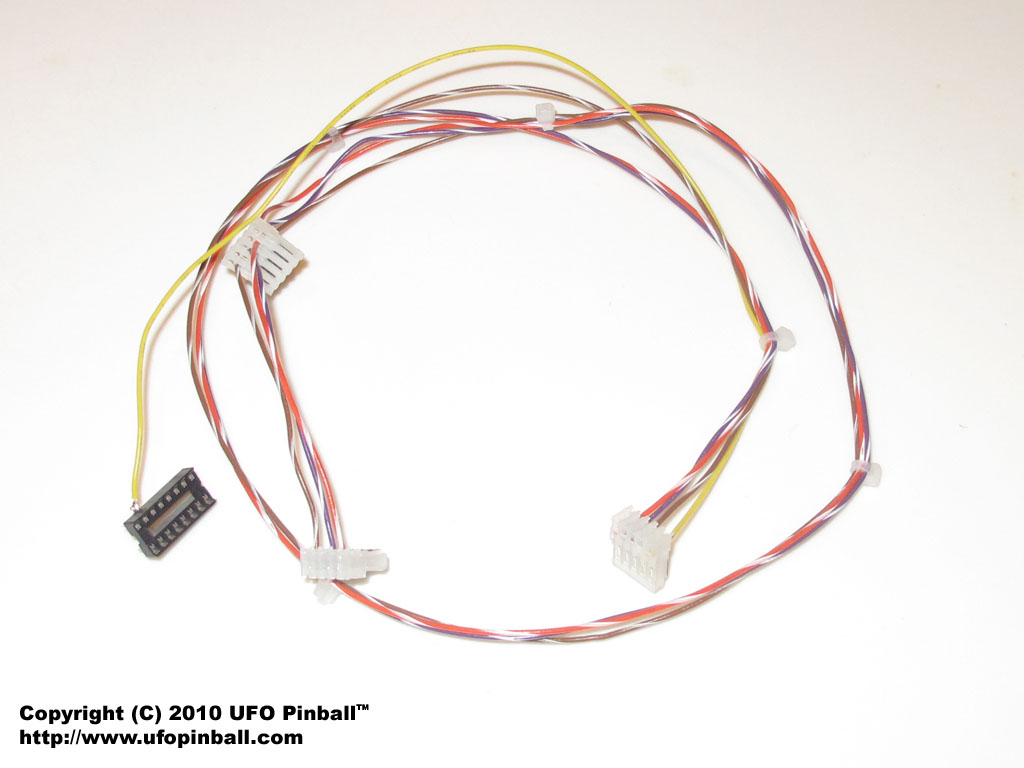 The end with two IDC plugs goes towards the Power Driver Board. Remove the current J110 connector and plug in the new wiring harness. Connect the old J110 connector to the Z-connector on the wiring harness (the male connector). Connect the remaining IDC connector to the middle connector (J18) on the left-edge of the AFM-Expansion board. 5) The 16-pin socket connects to the AFM-LED board. Gently remove the U4 chip (74HCT138) and install the 16-pin socket in the U4 location with the yellow wire on the bottom, facing left. Re-install the 74HCT138 chip into the new 16-pin socket. Chapter 1: Preparing your game Chapter 2: Installing the board and connecting the cables Chapter 3: Wiring up the Super Jets and Attack Hallway LEDs Chapter 4: Installation testing and jumper settings Chapter 5: Troubleshooting |