Attack from Mars
Mini-Saucer Expansion KitTM
How to Install the AFM Mini-Saucer Expansion Kit
Chapter 3: Wiring up the Super Jets and Attack Hallway LEDs
(Click on pictures to enlarge)
|
5) The Jet Bumper wiring harness is about 7 feet long with two IDC connectors on one end and three molex plugs on the other end: 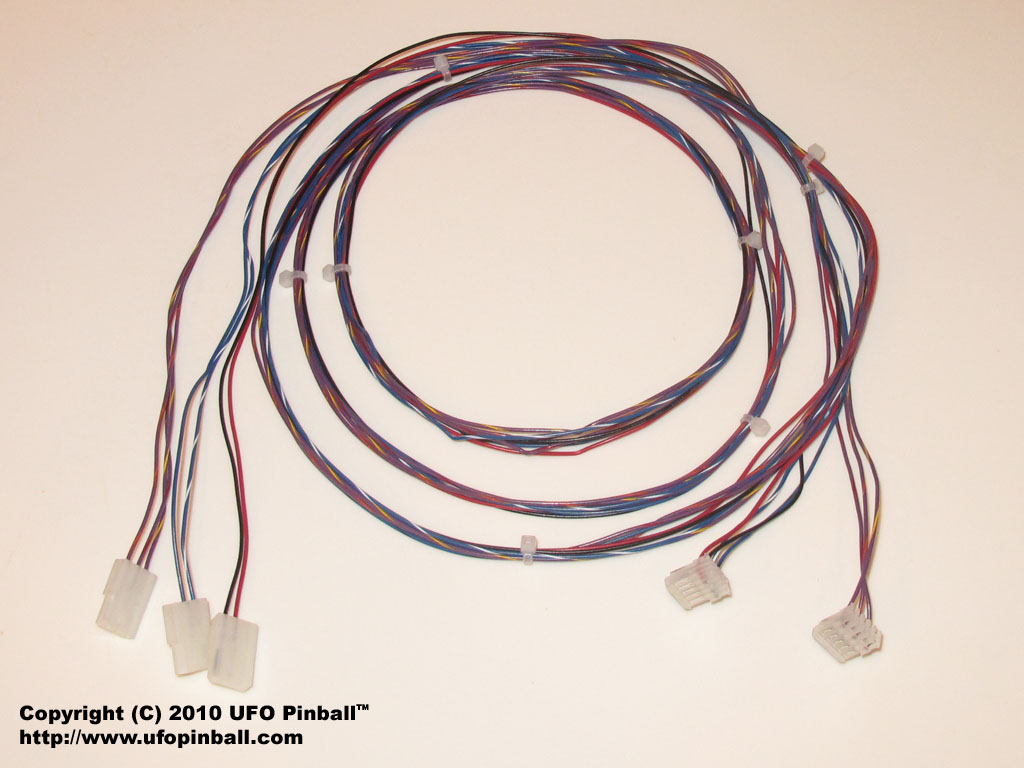 On the IDC end, the connector with the three violet colored wires goes to the upper header (J17) on the left-hand side of the AFM-Expansion board. The connector with the blue, red and black wires goes to the lower header (J19) on the AFM-Expansion board. Run the wiring harness down to the Jet Bumper assemblies on the bottom side of the playfield. 5a) Take the shorter harness with the three violet colored wires, these go to the Jet Bumper GI circuits: 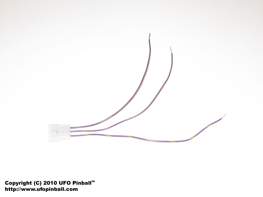 For each lamp, disconnect the solid Yellow or solid Orange lead for the Jet Bumper lamp and secure the wires using one of the yellow twist-caps. Use one twist cap for each jet bumper lamp, do not twist multiple lamp wires together. Next, solder the lead from the short wiring harness to the socket leg. The VIO/RED wire goes to the Left Jet, the VIO/ORG wire goes to the Bottom Jet, and the VIO/YEL goes to the Right Jet Bumper. Re-connect the 3-pin molex to the main harness, according to wire colors. Please note that the upper two Jet Bumpers should be on the Yellow/White-Yellow GI circuit, and the lower Jet Bumper should be on the Orange/White-Orange GI circuit ... if this is not so, the sockets will need to be re-wired. 5b) Take the shorter harness with the blue colored wires, this one goes to the Jet Bumper Flasher: 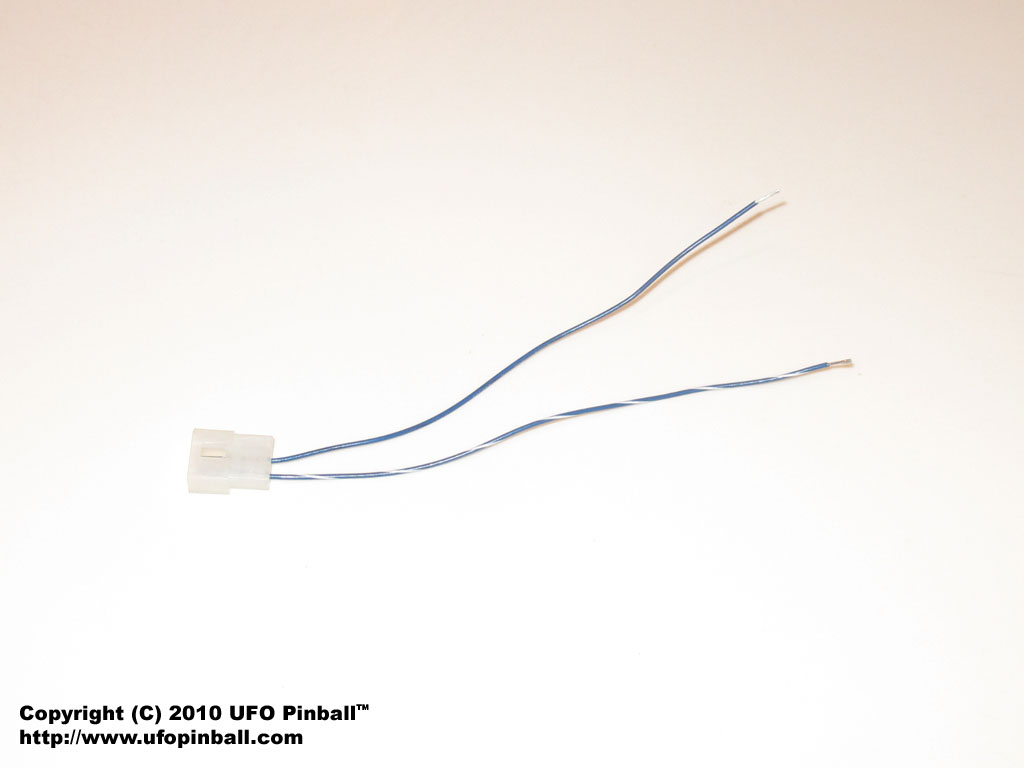 Disconnect the BLU/BLK wire from the #89 lamp socket, and connect it to the BLU/BLK wire with the blue twist cap. Connect the BLU/WHT wire to the #89 lamp socket. Re-connect the 3-pin molex to the main harness, according to wire colors. 5c) Locate the Jet Bumper Coil Switch Assembly, it is the shorter harness with the double-face foam tape attached: 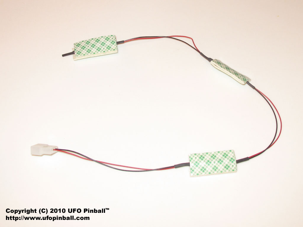 Peel back one side of the foam tape, and stick it to the bottom of the Jet Bumper Coil Assembly. Order does not matter, the switches are wired in parallel. Connect the 3-pin molex to the main harness, according to wire colors. 6) Locate the "Attack Hallway" LED assemblies. These are the smaller boards with eight LEDs each. The metal walls come in the smaller ziplock bag. Note: These instructions have been changed recently as a result of Service Bulletin #1. 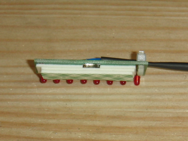 You'll need to remove the Mothership, and the plastics to the left and right of the attack hallway. Unscrew and remove the two metal walls located near the target bank. Place your original walls and screws in a safe place. Install the new metal walls using the provided #8 1/2" phillips-head screws. The new boards require a little more spacing behind the wall, making the 1/4" hex-head screwdriver a bit too big. The cable ends are marked L and R to indicate which board goes on which side. When in doubt, the cable should feed back towards the rear of the machine for each installed wall. Tuck the cables as best you can so as not to create shadows. Feed the cables down through the hole beneath the entrance to the center/lock ramp, and connect them to the AFM-Expansion board according to the L/R phone plug connectors. Finally, remove the protective film on the boards and attach them to the metal walls so that the LEDs shine through the holes. Chapter 1: Preparing your game Chapter 2: Installing the board and connecting the cables Chapter 3: Wiring up the Super Jets and Attack Hallway LEDs Chapter 4: Installation testing and jumper settings Chapter 5: Troubleshooting |
Back to the Main Page
Copyright © 2010-2023 UFO PinballTM
www.ufopinball.com