Attack from Mars
Mini-Saucer LED KitTM
How to Install the AFM Mini-Saucer LED Kit
Chapter 2: Connecting the wire harness
(Click on pictures to enlarge)
|
Now, it is time to install the wiring harness. The wiring harness is constructed using the same color-coded wires as are already in the game. The connections are also keyed to ensure the proper connectors go on the correct headers. To begin, you will need to locate header J0 on the AFM-LED board (this one's pretty obvious) ... as well as J138 and driver transistor Q25, both on the Power Driver Board. The exact connections are listed below.
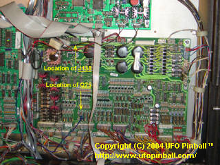
Locations of J138 and Q25 on the Power Driver Board (With the kit installed) First, take the connector with three wires and plug it into the AFM-LED board at header J0. Take the other connector (with only two wires) and route those cables down to the top of the Power Driver Board, and then to the right. Along the top of the Power Driver Board, locate connector J138. Plug the other connector in here. The board draws power here, directly from the Power Driver Board. 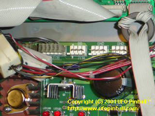
AFM Power Driver Board connector J138 (before) 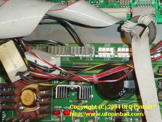
AFM Power Driver Board connector J138 (after) Once this is completed, you should only have a blue-purple wire left with a ring on the end. Take this wire and route it straight down, between the CPU and Power Driver Board. At the bottom of the Power Driver Board, begin pulling the wire to the right. About 1/3 of the way in, you should see banks of driver transistors ... the one you want is marked Q25. This connection is what links the AFM-LED board to the Mother Ship on the playfield. Specifically, it is linked to the tab of the driver transistor for the #906 flasher bulb under the green dome. If you are having trouble finding Q25, refer to the earlier guide. Insert the smaller screw provided, with the head of the screw facing the right, through the hole in the metal tab of Q25. There is not a lot of space to work with ... I had pretty good luck inserting the screw using a pair of needle-nose pliers, then using a small jewelers (or eyeglasses) screwdriver to turn the screw. The metal ring on the end of the blue/purple wire goes on next, followed by the nut that has the washer attached ... I had better luck just turning the screw, instead of trying to thread the nut on there. Make this connection hand-tight, and then double-check to make sure no metal parts connected to Q25 touch the metal parts on any of the nearby driver transistors. 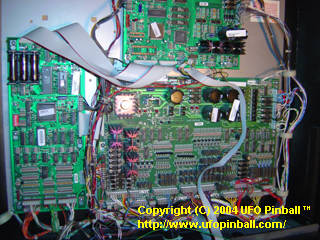
Overview of the Power Driver Board 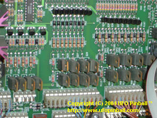
Close-up of driver transistor Q25 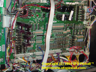
AFM-LED connector mounted to driver transistor Q25 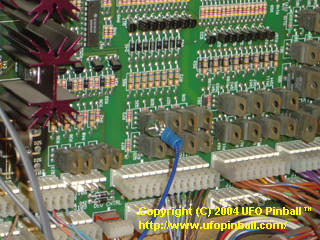
Close-up of Q25 connection 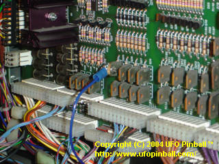
Close-up of Q25 connection (screw side) At this point, you may want to test the board to ensure all your connections are good. Turn on your game and the board should power up. In the upper-left corner of the board are three red LEDs. The top one should be solid and signifies power to the board. The middle one blinks and verifies that the system clock is functioning properly. The bottom one monitors hits to the Mother Ship. When a hit is detected on the Mother Ship, the third LED lights up for about half-a-second. If you wish to test hits to the Mother Ship, you can either play a game, or run the Flasher Test. To properly test this feature, you must close the coin door. If the flashers are not enabled (ie: high power cutoff switch is open), the circuit has trouble reading the Mother Ship, and the third LED may stay on indefinitely. Be sure to turn the power back off before continuing the installation. Chapter 1: Installing the board Chapter 2: Connecting the wire harness Chapter 3: Inserting the LEDs in the saucers Chapter 4: Remounting the saucers back in the game Chapter 5: Connecting the saucers to the board |