Revenge from Mars
Mini-Saucer LED KitTM

(Click to enlarge)
How to Install the RFM Mini-Saucer LED Kit
Chapter 1: Installing the board
|
The RFM-LED kit was designed to be non-intrusive. You can install the kit in your Revenge from Mars pinball machine without making any permanent modifications to your game. Complete installation should take an hour or so. While it can be accomplished as a 1-person job, it is probably worth having a second hand to help out ... plus, it's always more enjoyable to share the fun with a friend. 
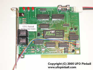
RFM-LED Board (Click to enlarge) The RFM-LED printed circuit board will be mounted in the backbox, just like any other board. First, turn off your game using the main cabinet switch, and wait for 5-10 minutes for things to discharge. Next, unlock the backglass, then remove the backglass assembly, and place it somewhere safe. Inside the backbox you will see a silver metal box where the main "brains" of the game live ... this is the CPU box. Some games may have zip ties holding this box in ... you will need to remove these. I believe the zip ties are intended to ensure that the box does not move during shipping, so replace them if you decide to move the game. Once your CPU box is free, gently lift it up and pull it forward ... it should swing downward and hang a little in front of the game. It should not be able to touch the flourescent light tube, but you can remove that and put it somewhere safe, if you really want to. Remove the cover of the CPU box and set it aside. On the front of the CPU box is a red button. This controls power to the CPU box only, and does not shut off things like the video monitor. We will not be using this button, so if you accidentally push it (and turn it off), you will need to push it again to re-enable power to the CPU. 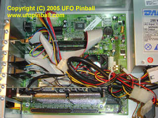
Revenge from Mars CPU Box (Click to enlarge) Inside the CPU box is the Pinball 2000 Cyrix MediaGX motherboard, and the Williams/Bally "prism" card with the Revenge from Mars ROM card attached. The prism card should be located in the middle slot, which is one of the two available PCI slots (white plastic slot). Towards the front end of the box is the ISA card slot (black plastic slot), which can accept a SMC 8416 ethernet card ... allowing you to hook up a computer and access some game information. On the other side of the prism card, towards the back end of the box, there is the second PCI slot ... this is where you will be installing your RFM-LED card. If your prism card is in this slot, you may need to move it back to the center slot ... otherwise, there may not be enough clearance to install the RFM-LED card. The RFM-LED card includes one power plug adapter that is pre-attached. The power plug is located in the upper-right corner of the board. On the bracket end of the card, there are two phone plugs where you will connect your saucer cords. Last, there is a "signal" connection that is fed through the metal bracket, and goes through the round hole towards the bottom of the bracket. To keep things neat, another pre-installed cable carries the signals just outside the metal bracket, and a molex plug is installed there to make it easier to install or uninstall the board. 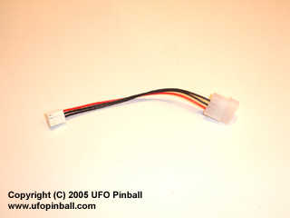
RFM-LED uses a standard floppy drive connector adapter (Click to enlarge) 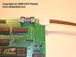
The RFM-LED power cord comes pre-attached (Click to enlarge) Now we are going to install the board. First, loosen the screw holding the metal "L" bracket next to the empty PCI slot, and remove the bracket. Install the RFM-LED card in the empty PCI slot, and secure it with the original screw. There are a lot of cables in this area, so you will need to be sure all of that is clear as you are installing the card, and verify that no wires are binding when you are finished. The RFM-LED card should not touch the Prism card. Once you have the card properly installed, you may connect the power plug. This is the internal cable with the red and black wires. It should be long enough to connect to any available 4-pin hard drive power connector inside the game, without you having to loosen the wire bundle. Keeping the original wires bundled helps to ensure better air flow, to keep your components cooler. 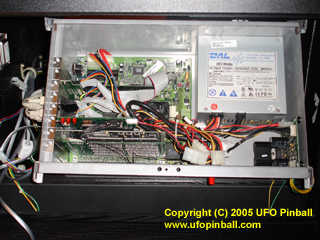
The RFM-LED board, properly installed in the CPU box (Click to enlarge) Chapter 1: Installing the board Chapter 2: Connecting the wire harness Chapter 3: Inserting the LEDs in the saucers Chapter 4: Remounting the saucers back in the game Chapter 5: Connecting the saucers to the board |
Back to the Main Page
Copyright © 2005 UFO PinballTM
www.ufopinball.com