Revenge from Mars
Mini-Saucer LED KitTM
(Click to enlarge)
How to Install the RFM Mini-Saucer LED Kit
Chapter 2: Connecting the wire harness
|
Now that we have the board installed, we will begin to work on the wiring harness. You will need to remove the back door of the backbox, as we will be running our wires up the back end of the game. Note that the video monitor carries very dangerous voltages and will hold a charge for several days after being turned off. DO NOT TOUCH ANYTHING NEAR THE MONITOR!! The wiring harness is a long length of cable that connects the RFM-LED board to the Power Driver Board, which is located on the bottom "floor" of the game. Locate the wiring harness and remove the twist-ties. One end has a 3-pin molex plug, this is the end that will connect to the RFM-LED board. The other end has two Mini-Fit Jr. connectors, that connect to the Power Driver Board. 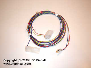
RFM Signal Wiring Harness (Click to enlarge) You will need to open the coin door and remove the topglass (put it somewhere safe), then raise the playfield. At this point, it is more helpful to have someone hold up the playfield as you work on the wiring harness. The Power Driver Board is covered by a dark shield. This lifts up so that you can access the board. On this board, there are two headers towards the lower-right corner that are unused. 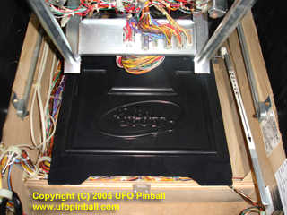
The Power Driver Board is located beneath the black shield (Click to enlarge) J110 is a 24-pin vertical connector. The Mini-Fit Jr. connector with the blue/brown wire goes here, with the tab facing the left side of the game. The connector should fit in very easily without any real force required. If the connector does not go in easily, something is probably wrong. J107 is an 18-pin horizontal connector. The Mini-Fit Jr. connector with the red/grey and yellow/violet wire goes here, with the tab facing the back end of the game. Again, the connector should fit in very easily without any real force required. If the connector does not go in easily, something is probably wrong. 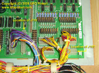
Revenge from Mars Power Driver Board (Click to enlarge) 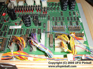
The RFM-LED Signal Harness, properly installed (Click to enlarge) Once you have properly connected the two Mini-Fit Jr. plugs, gently run the cable to the left, and then towards the back of the playfield. Bundle the RFM-LED signal harness along with the other wires in the various wiring clips. Route the cable up the back wall of the game. This is another situation where it is advantageous to have a second person to help hold the playfield, and/or feed the wire up the back wall of the game. Continue to route the wire through the existing cable clips, and run it up the left-hand wall of the game (this becomes the right wall if you are behind the game), then out towards the front. The signal harness should reach the mating 3-pin molex plug on the RFM-LED board, with some length to spare. The slack in the line is intentional, so that you can pull the molex plugs outward if you need to disconnect the RFM-LED board from the wiring harness. Connect the two molex plugs, noting the keyed plug and the colors of the wires. The connection can only be made in one way. 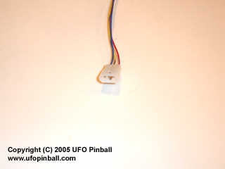
Close-Up of the short Signal Wiring Harness (Click to enlarge) Chapter 1: Installing the board Chapter 2: Connecting the wire harness Chapter 3: Inserting the LEDs in the saucers Chapter 4: Remounting the saucers back in the game Chapter 5: Connecting the saucers to the board |
Back to the Main Page
Copyright © 2005 UFO PinballTM
www.ufopinball.com